The vintage Jaykit FG-1a waveform generator.
Behold the new addition to my retro test equipment, the ridiculously rare Jaykit FG-1a (Function Generator - 1a). Not to be confused with the shivering Scottish street-mugger's colloquialism 'Och, gie's yer jaiket noo'. Obtained through actual twentieth century human interaction, an unexpected bonus item from a fine fellow named Richard, he offered me electronic riches.

I found no info regarding this function generator online, I don't know where else to look, all cyber stones have been turned. The internal clues suggest it was a self-assembly kit from 1979. In fact there are no general Jaykit references online at all, so I shall studiously allude to this antiquated apparatus for the benefit of the esoteric Earthlings. This page will be the soul source, an ambiguous article for folk to frivolously skip through.
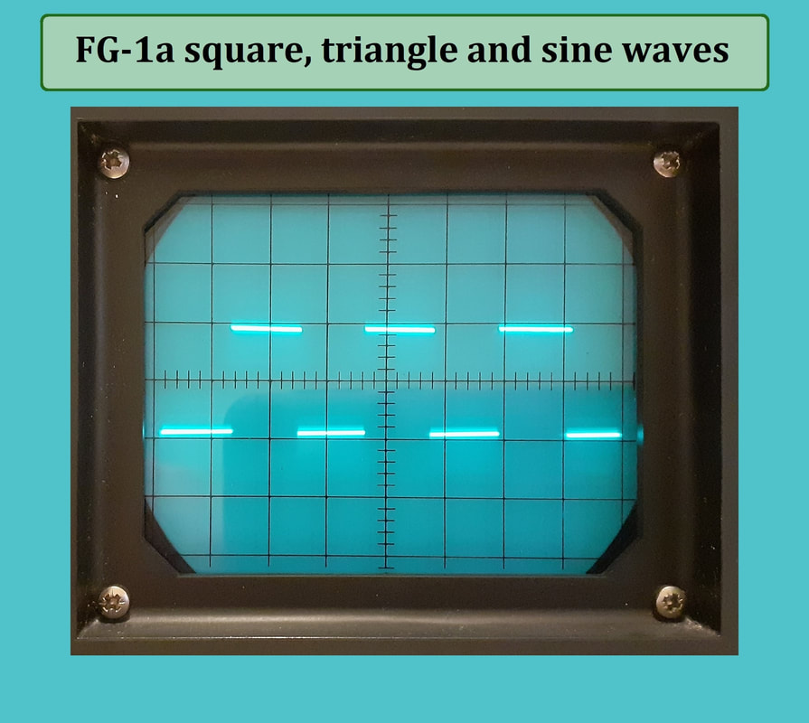
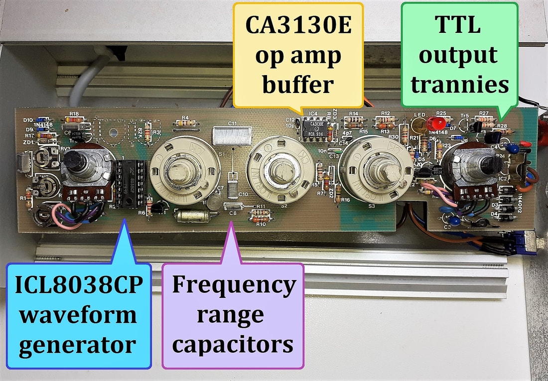
I built my 555 timer square wave signal generator, portrayed on the previous page, but it now has competition from this tri-wave treat. Built around the Intersil ICL8038CP wave generator chip, it churns out square, triangle and sine waveforms, allegedly from 1Hz to a 100kHz maximum.
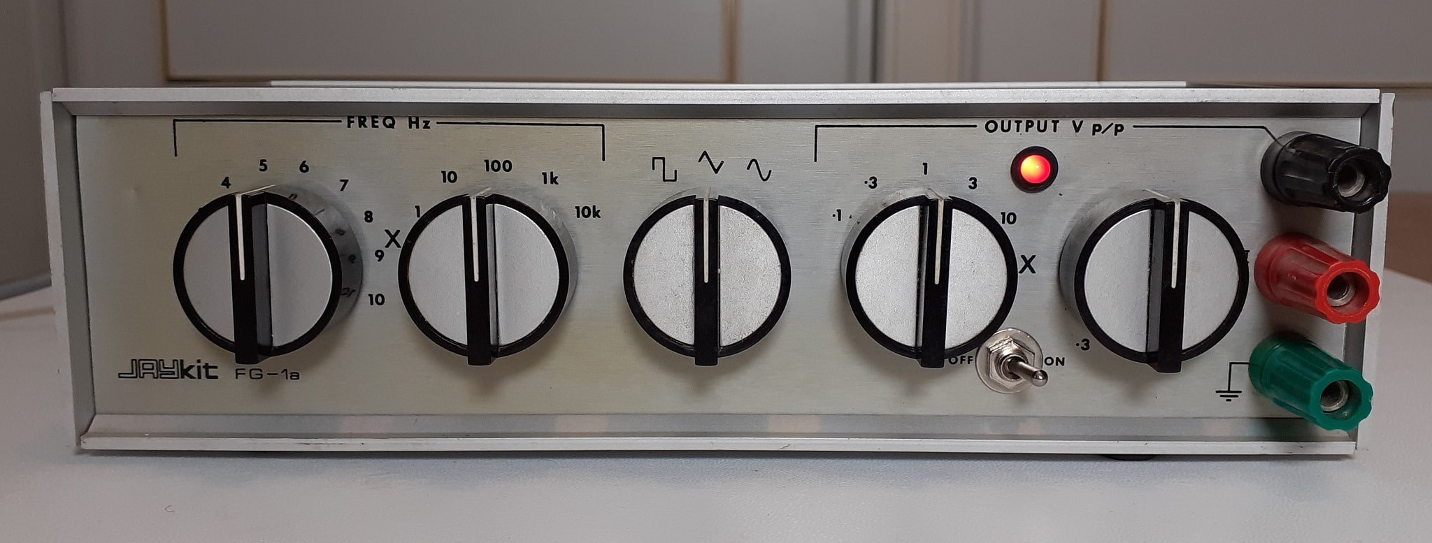
The front panel offers five frequency ranges, each range spans about three and a half octaves. When one of the quintet of range capacitors are switched into service, the low tolerance pesky polystyrenes produce somewhat irregular ranges, brazenly starting on ballpark figures, decimal precision being far from reality, but after all it's an antediluvian analogue DIY kit which does an excellent job.
It is of mainly aluminium construction, held together by the end-panel screws, with a black vinyl coated steel top and bottom measuring 233mm long, 127mm deep and 64mm high. It looks like the assembler had to drill their own case holes for the controls and transformer, I think the case was part of the original kit owing to the front adhesive decal.
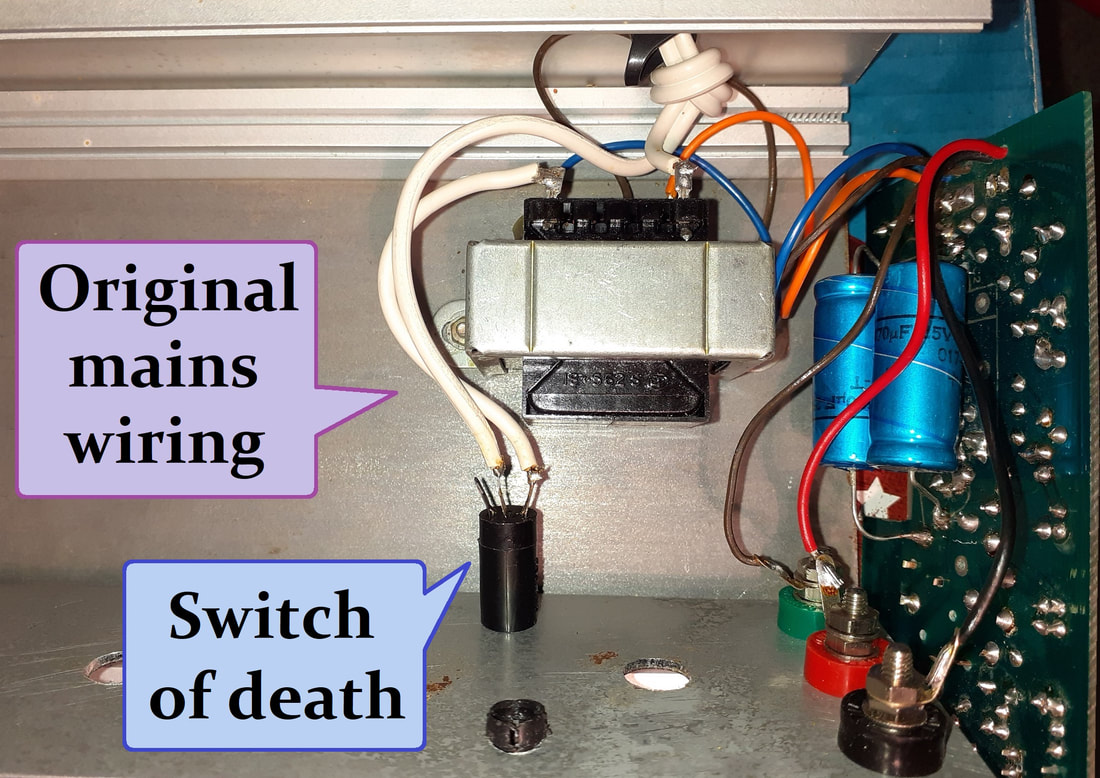
I replaced the dubious single insulated, non-earthed speaker-wire style mains lead which went straight to the hazardous PVC tape-insulated flimsy switch on the front panel, and chose to feed the 240V AC transformer primary directly, insulating exposed live connections with heatshrink sleeving, and rewiring the secondary (+/- 14.3V AC) bipolar supply to the circuitry, through a new DPDT switch.
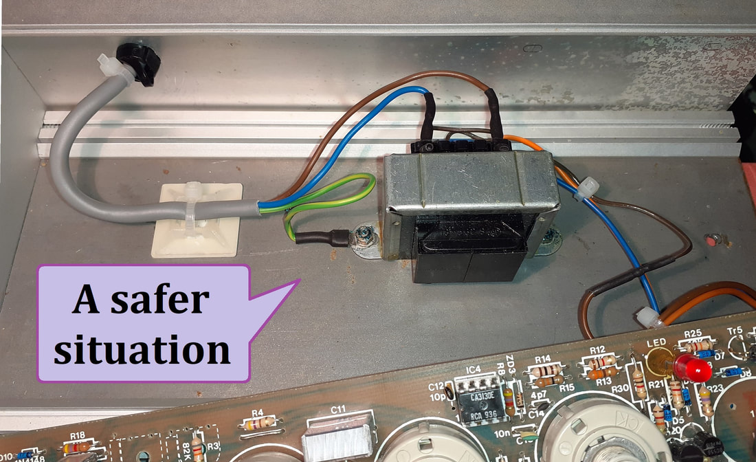
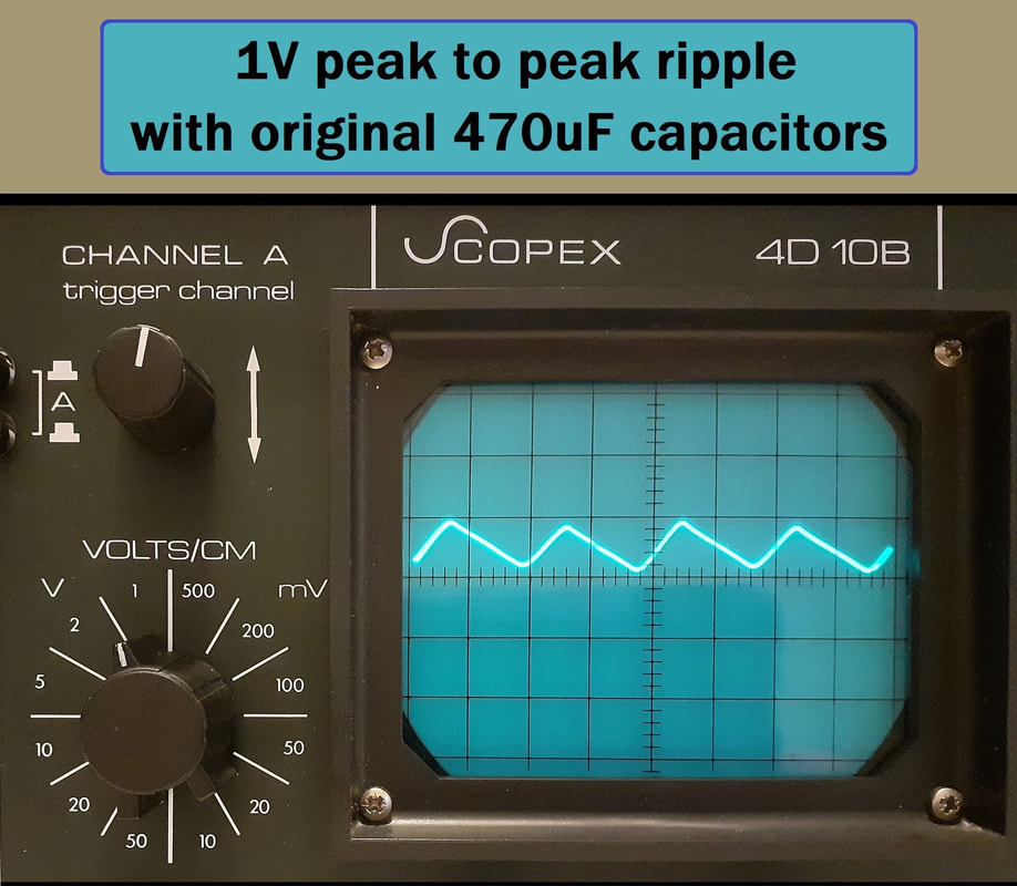
I made it much safer by choosing 0.5mm three core flex, fed by a 3 amp fuse, and earnestly earthing the very metal enclosure. The two pots were cleaned, the transformer shuffled away from the clumsily mounted capacitors, and abundant tinkering occurred. I replaced the two axial 470uF 25V smoothing capacitors mounted on the solder-side with new 2200uF 25V types, as 470uF is pathetically paltry.
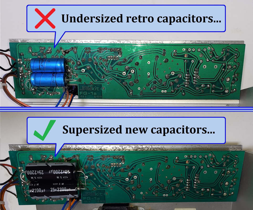
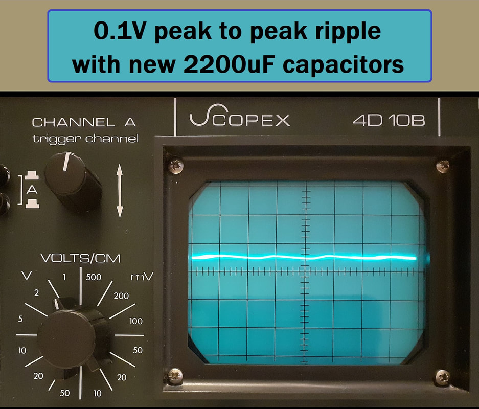
With my new retro scope on the 1V per cm setting, I can see the benefit of the larger smoothing capacitors. With the 470uF caps, the ripple across each voltage rail and ground is 1V. With the 2200uF caps, the ripple is about 0.1V, which is a most impressive improvement.
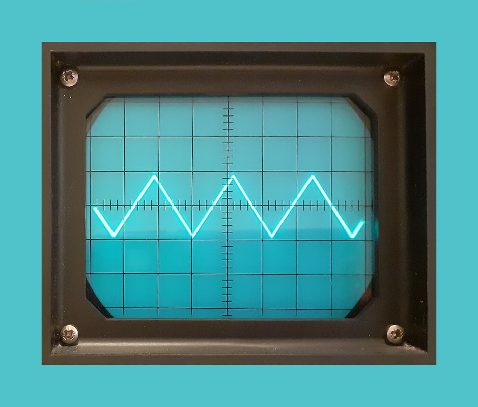
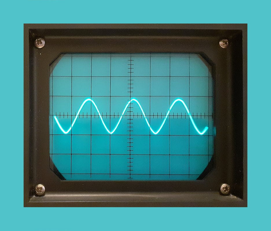
Having previously made a narrow range adjustable frequency triangle waveform using a dual op amp for an autopan effect, I know it's a challenge. The FG-1a just churns out splendid square and sine waves, and perfect triangle waves at all available frequencies.
The ICL8038 chip is a champ, and still available, it can currently be procured for less than three proverbial pounds. The eight pin chip on the PCB is a CA3130E, which is a 15MHz BiMOS op amp, and it serves as a buffer and a booster between the signal generator and the output section.
I'd say that for a kit, this gadget is pretty cool. Having fiddled, fondled and attempted perfection, I finally performed frequency tests with my beautifully retro, recently repaired, real oscilloscope, (courtesy of the forementioned legendary Richard, a scope webpage undoubtedly forthcoming on an internet near you).
Note to all - the fantastic Soundcard Scope 'free to hobbyists' program for PC gives up at 20kHz, and wasn't happy at the low end either, choosing to prioritise 50Hz mains buzz.
Note to all - the fantastic Soundcard Scope 'free to hobbyists' program for PC gives up at 20kHz, and wasn't happy at the low end either, choosing to prioritise 50Hz mains buzz.
The frequency section provides coarse and fine tuning, the lowest wave that I could squeeze on the real retro-scope CRT screen whilst employing the old fashioned formula (F=1÷T) was 6.7Hz, but the FG-1a went a touch lower. The highest reading was 86.9kHz, I am satisfied with this random range, courtesy of the five capricious capacitors.
The ranges of x1, x10, x100, x1k and x10k are the starting frequencies in Hz, the fine tune control seems to be the multiplication factor, as is hinted at by the dubiously positioned 'X' at the end of the 1 to 10 scale. For example, if the 10k range is selected and the fine tune control is on six, we should have a 60kHz, but in reality it will be miles out, it's dependent on the tolerance of the pernickety potentiometer and the capricious capacitors.
The three position waveform switch selects the super wave shapes.
The output section suggests switchability from 0.1 to 10V peak to peak, tweaked with a fine voltage control.
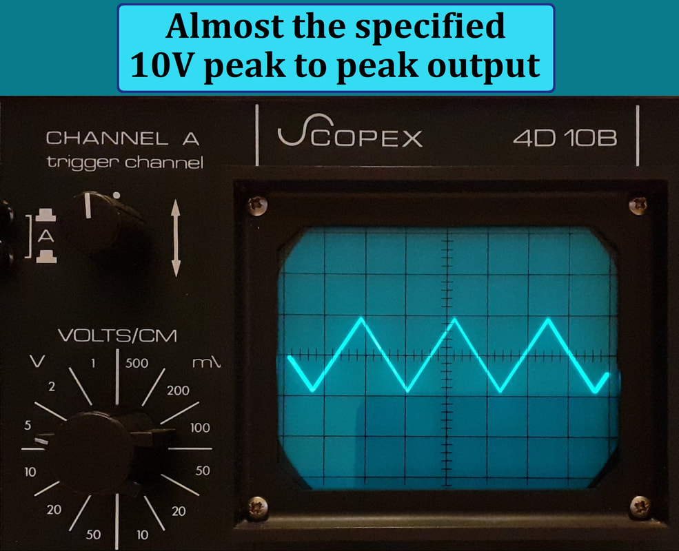
When testing the triangle on the retro scope, the 10V peak to peak setting was indeed - just a smidgen under 10V.
Again there is another vague 'X' by the fine volt control, this is marked from 0.3 to 1, so this must be for voltage reduction, where '1' is the voltage as specified by the voltage switch, and turning the control anti clockwise reduces the output level down to about a third of the selected voltage.
The green terminal is the common or ground, the centre tap zero volt rail.
The black terminal is the main adjustable signal generator output, with all the bells and whistles.
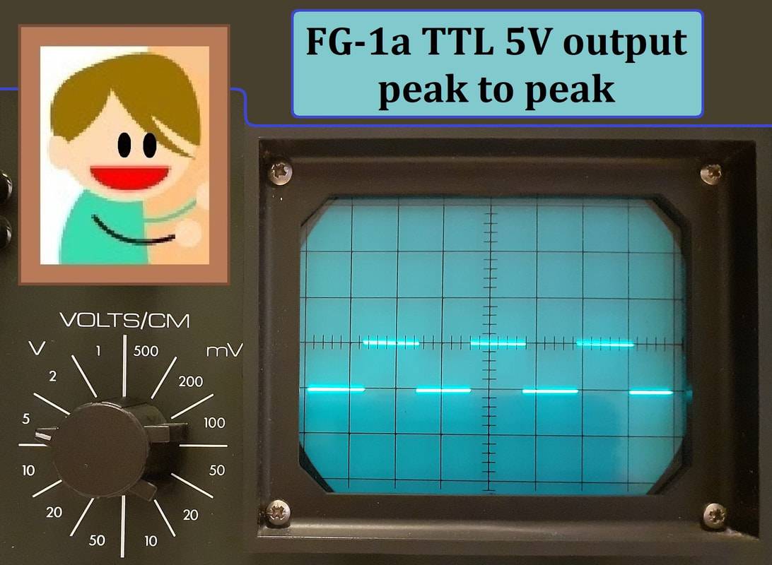
The red terminal is the TTL output, this is only a square wave function which can be frequency adjusted, but it's fixed by two transistors at the 'transistor-transistor logic' level for connection to TTL chips etc.
The TTL output proved to produce a 5V peak to peak square wave.
Again there is another vague 'X' by the fine volt control, this is marked from 0.3 to 1, so this must be for voltage reduction, where '1' is the voltage as specified by the voltage switch, and turning the control anti clockwise reduces the output level down to about a third of the selected voltage.
The green terminal is the common or ground, the centre tap zero volt rail.
The black terminal is the main adjustable signal generator output, with all the bells and whistles.
The red terminal is the TTL output, this is only a square wave function which can be frequency adjusted, but it's fixed by two transistors at the 'transistor-transistor logic' level for connection to TTL chips etc.
The TTL output proved to produce a 5V peak to peak square wave.
I thank Richard for this unexpected treat, it has been keeping me out of trouble. Being a bit autistic and stuck in the past, this kind of retro relic floats my boat, and shall be cherished and kept as a useful memory of the disappointingly distant days of electronic hobby happiness.
