It's DJ's lead, a Super Bass Reduction Lead..
I'm using a dinky little Behringer Eurorack UB-1202 mixer which only has tone controls for the first four mono channels (or 2 stereo with panning), the remaining 8 channels (4 stereo or 4 pannable mono) have no tone controls.
I find that the bass level is too high on these latter channels to complement my pernickety piano, and it's not possible to sufficiently cut this bass on my output amplifier without having to crank up the bass of my piano to falsely equalise everything, so I've created the super efficient 'Super Bass Reduction Lead'.
This is a passive un-powered device using the convenient reactance of the resin dipped capacitor and the pseudo load of the trusty resistor. It's a brilliantly basic circuit known as a first order - high pass filter.
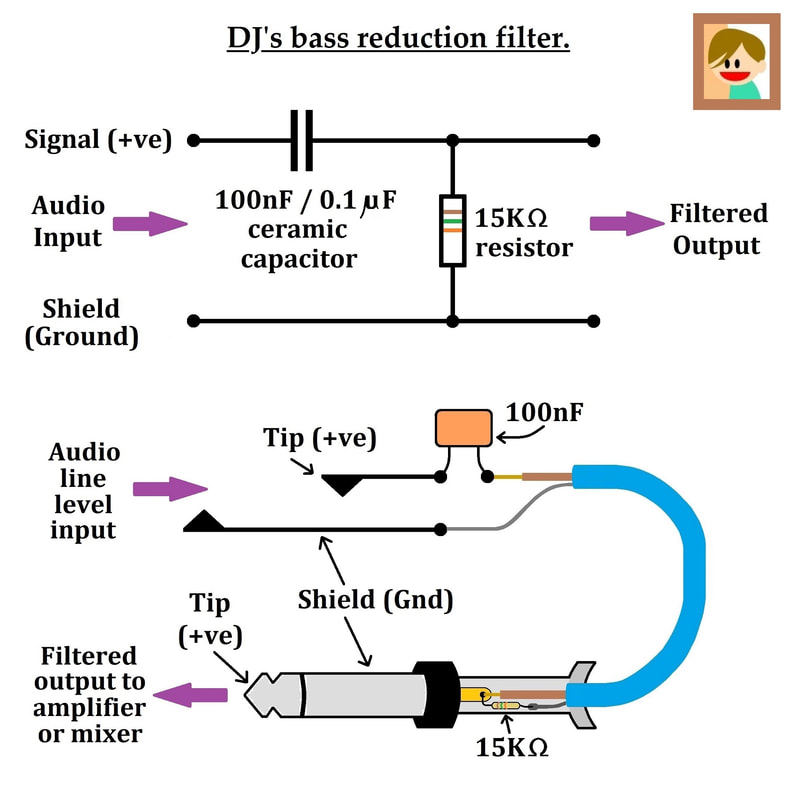
Simply expressed, a high pass filter allows frequencies above the cut-off frequency to pass through, whilst blocking the ear-offending low frequencies beneath the cut-off frequency.
It is not cool to have a digital acoustic piano sound, painstakingly tweaked and tamed by the 31 band graphic equaliser, and then have the drum machine booming out bassy kicks and kits.
I could solve this by using my ten tonne massive Maplin PAM-1240 Mixer, but it's a big boy - and I'm striving for minimalism.
I could solve this by using my ten tonne massive Maplin PAM-1240 Mixer, but it's a big boy - and I'm striving for minimalism.
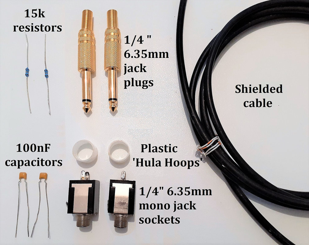
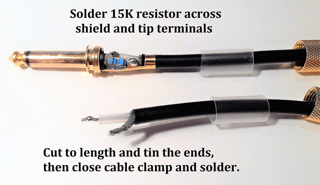
Assuming you use 1/4 inch mono jack leads, you just need a mono plug, a mono socket, a small capacitor, a 1/4 watt resistor and a foot of shielded cable (around 6 - 7mm diameter) for each Super Bass Reduction Lead.
Rather than needlessly grappling with tricky mathematical formulae, I perfected the capacitor and resistor values with experimentation and ears, then confirmed my findings using my graphic equaliser and finally an online R-C High pass filter calculator.
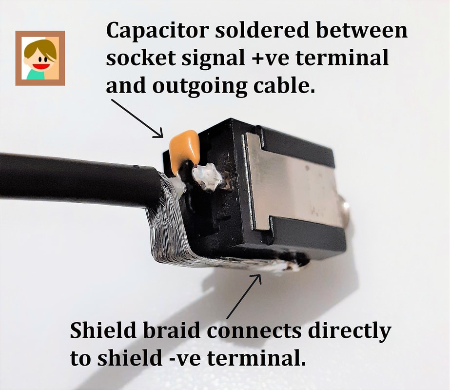
A small 100nF resin / ceramic capacitor will remove the thunderous thumps and thuds below 100Hz, whilst maintaining the clarity and saving my speakers.
The 15k resistor has a minimal effect on the cut-off frequency, but it provides a suitably mellow impedance for your mixer or amp to interact with, as the capacitor obscures the original impedance of your input device.
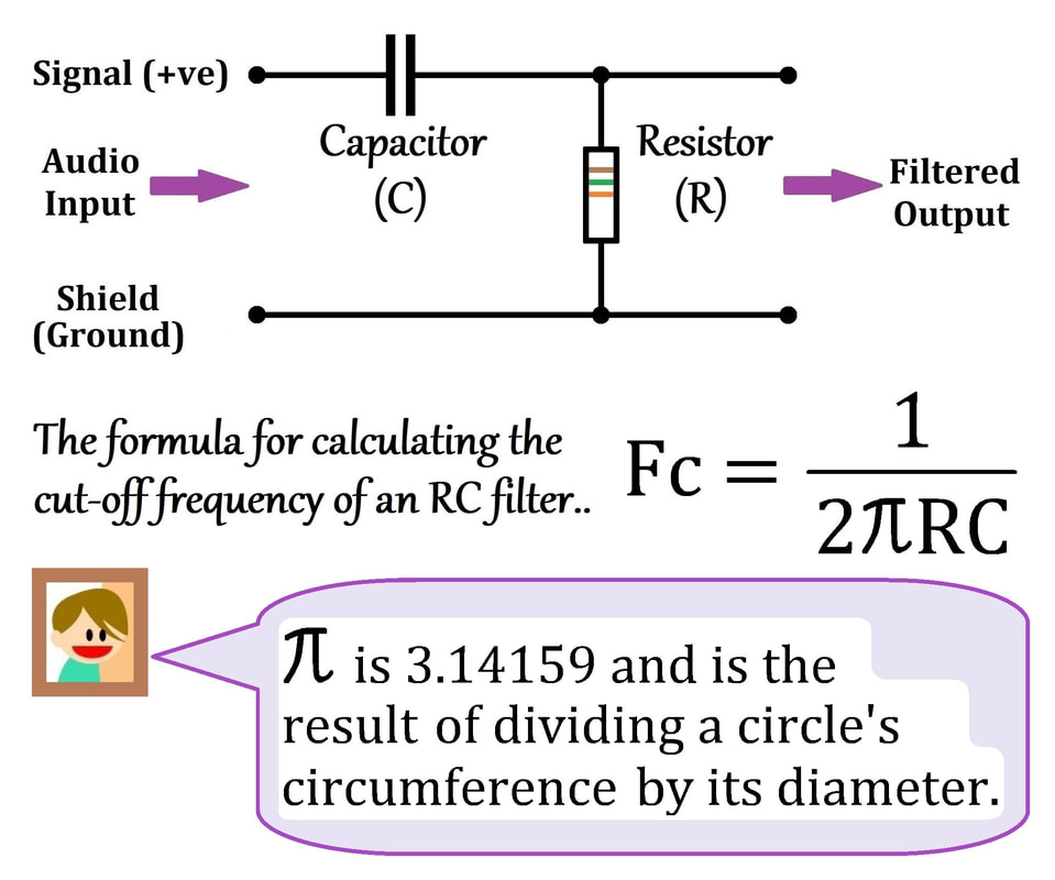
Using an on-line calculator we could avoid 'The Science' and find that the cut-off frequency of my component choice is 106Hz. This sounds good, the drums are much lighter and clearer to my ear. The nature of the cut-off curve (called the Bode Plot) is that frequencies below the cut-off frequency are still passed but at a logarithmically reduced rate, this is excellent audio news.
I shall provide some capacitor choice examples to enable a simple understanding of its relationship to cut-off frequency, within the realms of line-level audio high pass filters. (Tweeter maths is based on much lower resistances but uses the same formula). The higher the capacitor value, the lower the cut-off frequency, and vice versa.
80nF capacitor + 15k resistor = 132.7Hz
100nF capacitor + 15k resistor = 106Hz
120nF capacitor + 15k resistor = 88.5Hz
150nF capacitor + 15k resistor = 70.8Hz
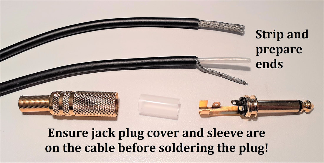
Hopefully the homemade circuit diagrams and photos are sufficient to assist the solitary person that actually wants to construct the 'Super Bass Reduction Lead'.
In case you're wondering, the 'plastic Hula-Hoops' were two of many that I salvaged from a clapped-out paper shredder, they are just something fill with epoxy resin to make a neat job.
In case you're wondering, the 'plastic Hula-Hoops' were two of many that I salvaged from a clapped-out paper shredder, they are just something fill with epoxy resin to make a neat job.
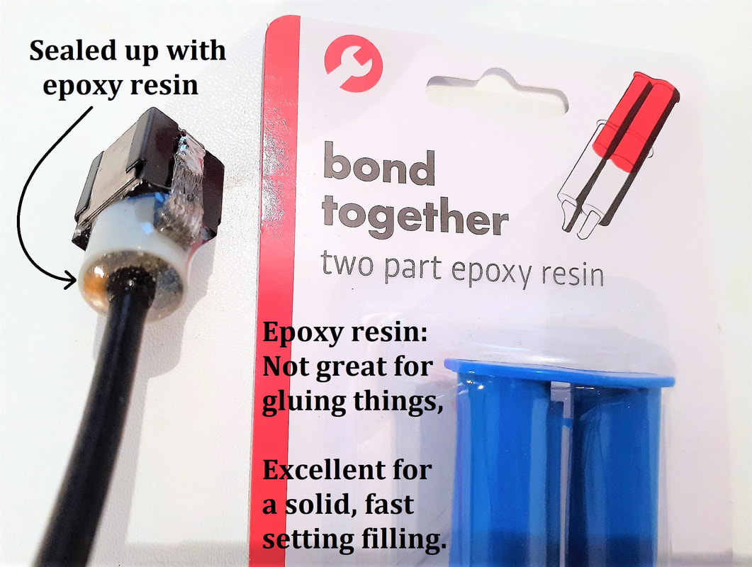
Depending on your choice of jack socket, you must ensure that epoxy does not seep into the socket or prevent a plug from entering its full insertion depth. I used electrical insulation tape over an improvised plugged-in jack plug to allow space for a real plug to enter, once the resin has set.
The heat shrink sleeving obscures and insulates any exposed connections. An in-line socket could look better but it would be difficult to squeeze the capacitor between the centre core and the tip terminal.
The heat shrink sleeving obscures and insulates any exposed connections. An in-line socket could look better but it would be difficult to squeeze the capacitor between the centre core and the tip terminal.
It's important to mark the input or output of the 'Super Bass Reduction Lead', so you know which end the resistor is.
The lead will still filter the bass if it's the wrong way around, but the purpose of the 15k resistor (which I've located in the jack plug) is to offer an impedance to your mixer's input, otherwise you may lose some audio energy from the source device.
The lead will still filter the bass if it's the wrong way around, but the purpose of the 15k resistor (which I've located in the jack plug) is to offer an impedance to your mixer's input, otherwise you may lose some audio energy from the source device.
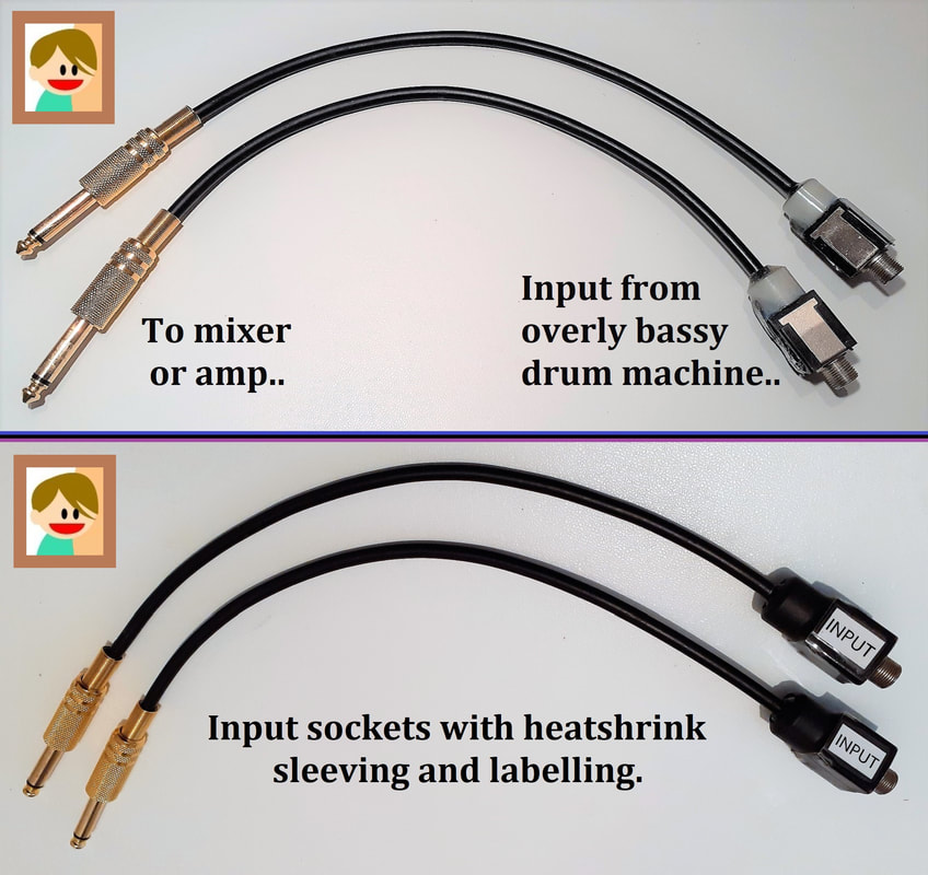
The advantage of the 'Super Bass Reduction Lead' is that it's a short and simple extension to a jack lead, removable, interchangeable and discreetly concealable.
I have previously made a pair of these which featured a miniature slider switch which selected either 100nF or 133nF, which switched a 33nF in parallel with the 100nF.
133nF gave the option for a touch more bass, if needed, still employing the 15k resistor as a pseudo load.
Capacitors in parallel simply add the two capacitances together, capacitors in series mysteriously reduce the total capacitance according to an intriguing formula.
