Making use of junk PC speakers and the antediluvian 555 timer.
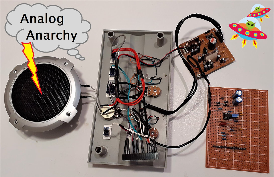
Behold, it's the butchery of a Packard Bell FPS-100 computer speaker 'system'. We all hold external PC speakers in contempt for their cable tangle factor. I bought this crappy cow from Feebay for £16 all in, I fancied the accompanying flat NXT satellite speakers which plugged into this 'Sub-box'..
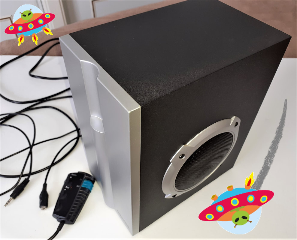
These turned out to be rattling rubbish, the flat sound panel is the most corny corrugated plastic ever, so I instantly dismantled them to extract the pathetic three watt transducers.
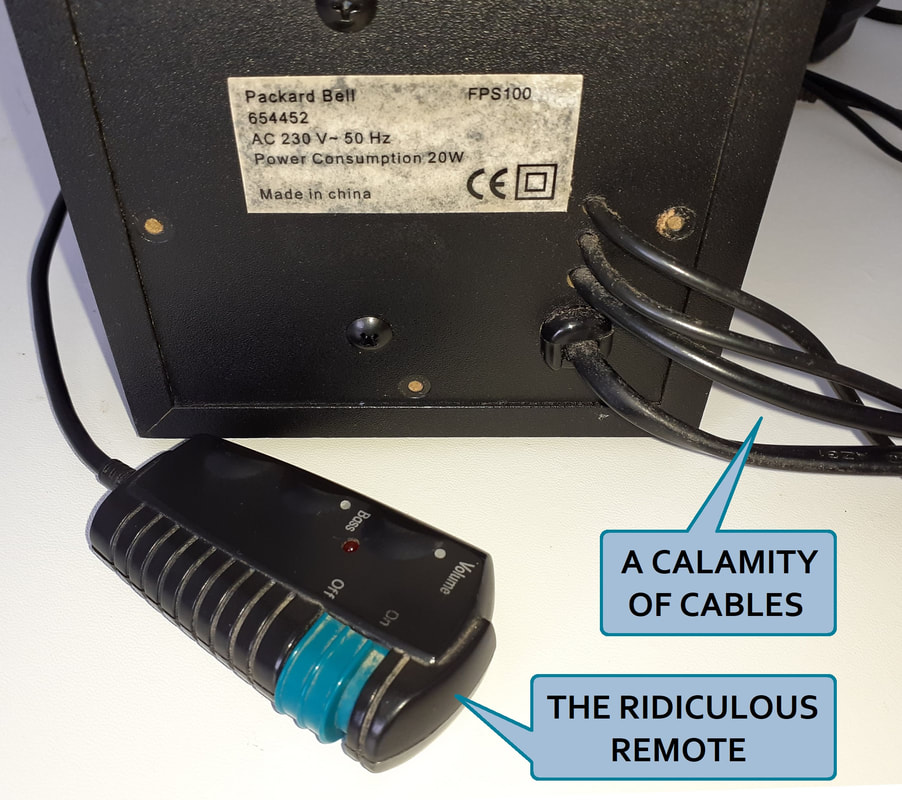
In the meantime, the sub-standard so-called Sub-Speaker with its ridiculously pointless 'not very remote, utterly clutterly volume control' languished in the loft until inevitable inspiration struck. I am not wasting £16 and then battling with being a mug.
This ephemera must endure extreme 'End Times' experimentation, the tacky tat will be tortured and tweaked to transmit testing tones.

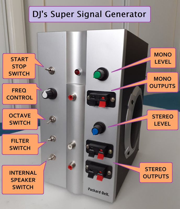
I had been playing with the outdated 555 timers I obtained to contact the dead, but became distracted. I created a splendidly stable six octave square wave generator with bonus features.
My vision was to create a signal generator with a mono output for testing speakers and stuff, and a stereo output for testing amplifiers and things, all perfectly possible with the Packard Bell pile of poo.
This will be a most useful and suitably sized, self-contained signal source, neither specific frequency selection or a perfect waveform is of particular importance. Electronic imperfection is inevitable.
It's highly unlikely that anyone else will be trying this with this damp squib amp, so tedious details will remain housed in my head, but I'll reveal my school-boy standard signal generator schematic and the noteworthy features.
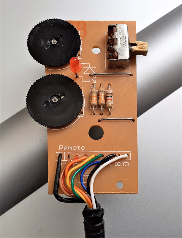
The first task was to remove the outrageous remote and imitate its small circuit board, easier said than done. There's a tiny but conventional three terminal 10k pot for the 'bass' volume, and the weirdest dual-(ish) 10k pot for the stereo satellite speakers, and this piddly five terminal dual gang pot makes no sense, and remains unfathomable.
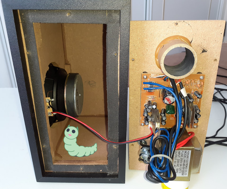
I gave up and found the pinout of the two ICs, a pair of obsolete TEA2025B amplifier chips, and conceived a more sensible way of connecting conventional volume controls which will be mounted on the signal generator, not on a clumsy cable. This chip seems to have fixed amplification and one must alter the input level, to achieve the output volume. One simply routes the output signal from the signal generator through the pots, through some DC blocking capacitors, and straight into the amp ICs.

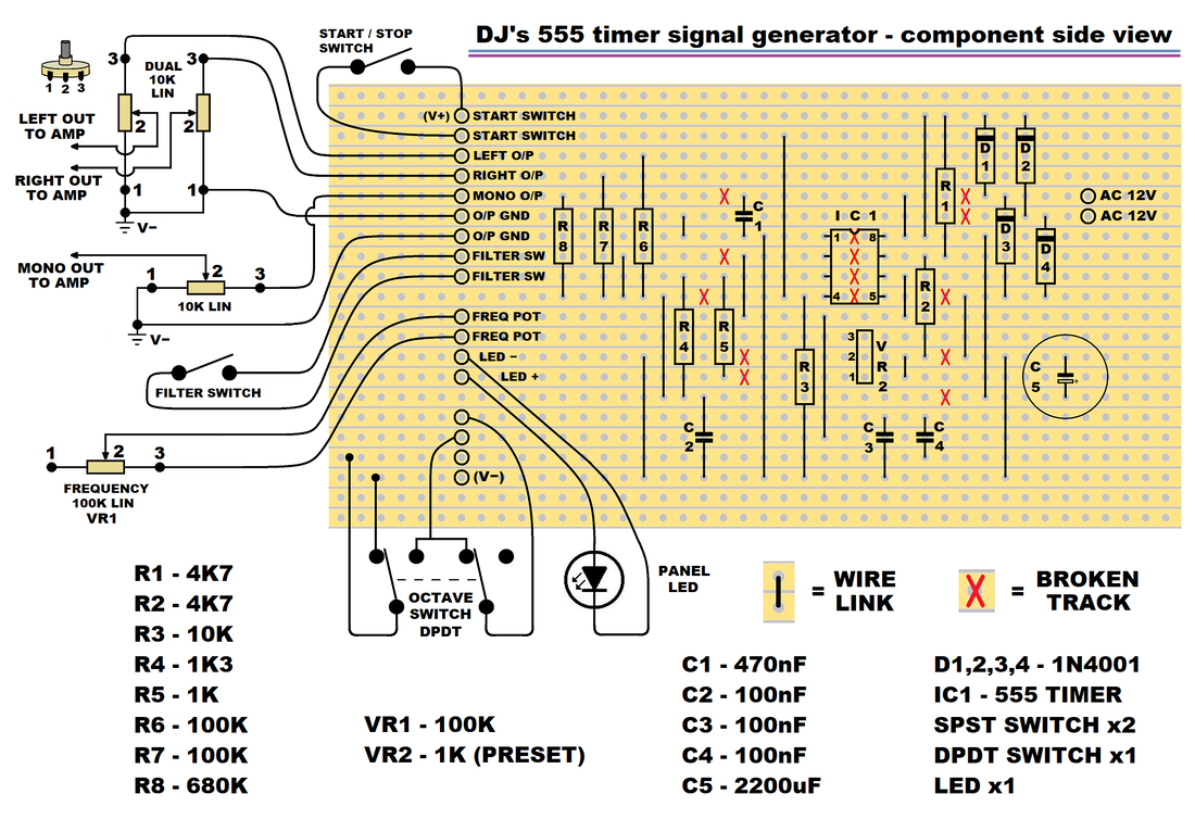
The pathetic flat speakers were not speakers, but filtered by tiny capacitors on the PCB to create tinny flimsy tweeters, the capacitors were clawed out. The piss-poor pads on the Packard Bell PCB from whence the wires to the volume controls were desoldered, couldn't wait to tear off, requiring the installation of a detachable header strip and some PCB track repairs, but this strengthened both the connections and my determination to build the best budget 'End Times' oscillator ever.
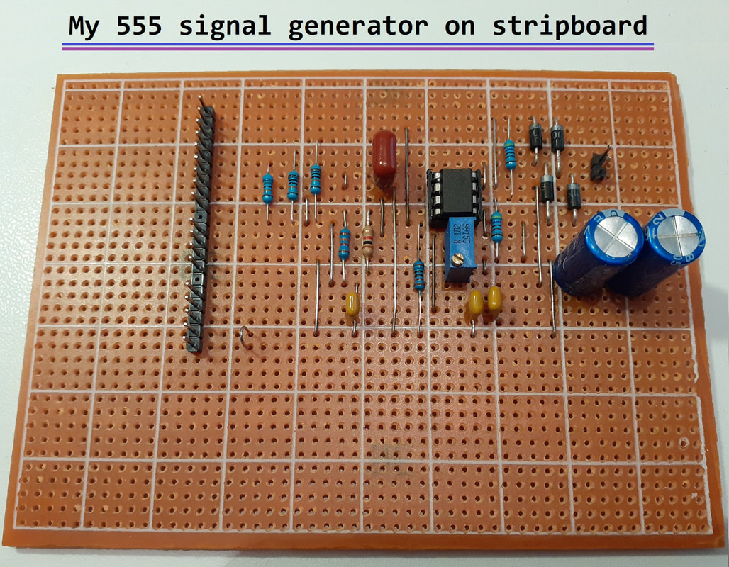
Choosing to re-live my youth before the impending apocalypse, I bought stripboard to build my perfected 555 signal circuit upon, having designed the layout. It worked like a dream, the problem I had was tapping into the built-in Packard Bell power supply to power both signal generator and amp. Plenty of low-level mains buzz modulating the squealing square wave, an impure tone to torment. This was overcome by adding a dedicated diode bridge and double smoothing capacitors for the 555 circuit, then incongruously connecting its ground to the amp's ground, and all was well.
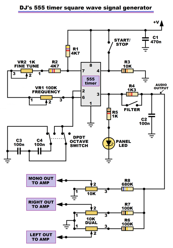
My internal transformer gives 9V AC, so I added the diode bridge, but this can be omitted. The circuit can be comfortably run on 5 to 15V DC. Resistors R6, R7 and R8 are there for compatibility with my amp, you may desire a different configuration or values.
My internal transformer gives 9V AC, so I added the diode bridge, but this can be omitted. The circuit can be comfortably run on 5 to 15V DC. Resistors R6, R7 and R8 are there for compatibility with my amp, you may desire a different configuration or values.
With the 555 in self-oscillating astable mode, the frequency range is set firstly by the chosen capacitor value between pins 2 and 6, and ground. Then, the larger the frequency pot, the greater the sweep range, but I found that a 100k pot gave me four octaves with good control. More resistance gives a wider range and lower frequencies.
The nature of the 555's logarithmic response to resistance ideally requires a reverse logarithmic pot, but I chose a larger bodied 24mm pot for its longer carbon track, 100K linear (actually 117K) pot. I wasn't going to spend a packet on an ultra-rare pot! You can get more range (but less accuracy) with a 200K pot but the slightest turn makes for spurious selection. 100K works well, even at the 'squeezed together' higher frequencies.
The circuit values were all chosen around this pot, so your pot may yield different results, mainly the octave range and the value of the fine-tune trimmer. I included a multi-turn 1K fine tune trimmer to perfectly reduce the full range of the frequency control to exactly four octaves.
The circuit values were all chosen around this pot, so your pot may yield different results, mainly the octave range and the value of the fine-tune trimmer. I included a multi-turn 1K fine tune trimmer to perfectly reduce the full range of the frequency control to exactly four octaves.
Regarding the capacitor between pins 2 and 6, and ground - if we halve the value, the pitch doubles (up one octave), a nice linear relationship. Thus I cunningly devised the two octave switch which extends my four octave range to six, by using two 100nF capacitors and a DPDT switch.
When the switch is in the up position, it connects the capacitors in parallel to ground, creating 200nF. When in the down position, it connects them in series to ground, creating 50nF, halving and halving again the capacitance and raising the pitch by two octaves.
One must match the capacitor pair well, find two with exact values for the best tuning, which can be done by ear.
By holding pin 4 to ground through the 10K resistor stops the oscillator, then by switching pin 4 to positive starts it up. A convenient method of pausing the signal generator without having to adjust or disconnect anything.
The filter switch shorts out the 1K3 resistor which is part of a simple low-pass R-C filter on pin 3's output. This curves the corners of the square wave when switched in, and reduces the rasping tone by reducing the harmonics.
The internal speaker is connected to the mono output of the amp, to give a monitor of the frequency. The internal speaker switch gives the option to disconnect the speaker, whilst the signal is still available at the outputs.
As I didn't have an oscilloscope at the time of building this, I downloaded the highly recommended, fantastic and free 'Soundcard Scope' on my Windows 10 laptop. To prevent blowing up my stereo soundcard I built a signal attenuator using a 1M pot with an input and output capacitor to block DC, and bingo! (I found that the recommended reversed diode protection pair just stopped any signal reaching the PC).
Amplitude levels are unlikely to be accurate, but you can see the exact waveform and the frequency is displayed precisely.
Amplitude levels are unlikely to be accurate, but you can see the exact waveform and the frequency is displayed precisely.
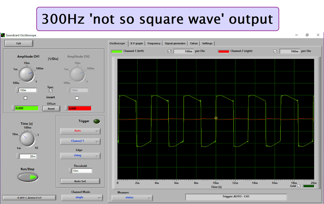
Utilising the Soundcard Scope program, I discover that my crude device oscillates from 28.3Hz upto a piercing 1.86KHz, a suitable audio range for testing things. The screenshot displays a so-called square wave at 300Hz. The waveforms at all frequencies have lost their lagging edge, like a busted ramp generator, probably a consequence of circuit capacitances, since connecting it to the Packard Bell-End amplifier PCB. With the filter switch on, the waveform is similar to a shabby sine wave.
The amp feeds out to a mono speaker connector at full level, and to an RCA connector via a 100K resistor, for an easier adjustment of a Line-Level friendly output (0.316V AC RMS).
The amp also separately feeds out to stereo speaker connectors at full level, and to RCA connectors via 100K resistors.
The amp feeds out to a mono speaker connector at full level, and to an RCA connector via a 100K resistor, for an easier adjustment of a Line-Level friendly output (0.316V AC RMS).
The amp also separately feeds out to stereo speaker connectors at full level, and to RCA connectors via 100K resistors.
Overall, this machine is marvellously mediocre, but when I need to test a speaker or inject a signal into something, I have the power of immediate convenience. It's better than the original Pack-O'-Shite 'Bell-End' box of bollox. One can now create a constant woefully wailing waveform and squirt it in a circuit under scrutiny, and possibly reap reasonable results.
